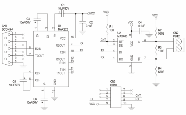
A typical RS485 network can operate properly in the presence of reasonable ground differential voltages, withstand driver contentious situations, provide reliable communications in electrically noisy environments (good common mode rejection using twisted pair cable, shielding provides additional protection), and support thirty-two or more (many IC manufacturers have 1/2, 1/4, 1/8 unit load devices) drivers and receivers on the line. These standards are widely adopted and supported, making them a good choice for many applications. Remote Monitoring and Control: RS485 allows remote monitoring and control of lithium batteries in various applications. The QScreen allows the details of the synchronous communications protocol to be customized for compatibility with a variety of peripherals. The RS485 standard allows the user to configure inexpensive local networks and multidrop communications links using twisted pair wire. Twisted pair wire with a characteristic impedance of 120 ohms is recommended with 120 ohm termination at each end of the communications line.
See the section on grounding for a discussion of this "extra wire". You can see there are potential problems here. This can be used for the sender to confirm that the data was received correctly, or for the user to see what data was sent. For example, an Automatic RS232 to RS485 converter, could be connected to a computer's RS232, full-duplex port, and transform it into an RS485 half-duplex, multi-drop network at distances up to 4000ft. Converters in most instances, pass data through the interface without changing the timing and/or protocol. RS485 and RS232 are widely used serial interface standards for communications in embedded systems, industrial automation and other applications requiring simple point-to-point or multi-drop connectivity. As these examples illustrate, optimal applications of RS485 vs RS232 align closely with their technical characteristics and trade-offs. A three-post jumper located between the third socket and H6 configures the primary serial port for either RS232 or RS485 operation. Now in the loop, we check if there is anything available on the serial port and then read the data and since the incoming data is an integer, we parse it and display on the connected LCD. It does not specify or recommend any data protocol.
RS232 was developed in the 1960s, and among other things, specified an electrical standard, a protocol standard, handshaking, what is rs485 cable and connector pin-out. A: The differential signal method in RS485 is an improvement over the RS232 serial communication. Unloaded driver output differential voltage can be as high as ±6V. EIA-485 only specifies electrical characteristics of the driver and the receiver. While RS485 is a 2-wire standard, it does offer 32 nodes on a network, on the other hand RS422 (a 4-wire standard) only specifies up to 10 nodes. Yes, RS485 can operate in a 2-wire half-duplex configuration where the same pair of wires is used for both transmitting and receiving, or in a 4-wire full-duplex configuration where one pair of wires is used for transmitting and another pair for receiving. 12K vs. 4K) many people refere to 4-wire RS485. The receiver load impedence is 12K ohms (or higher) and transmitter "leakage" current is ±100µA (or less) in either the powered or unpowered state. In general, many current applications for RS232 use only the electrical standard (3-wires, TDX, RXD, Common) and connector pin-out. They have Shielding Jacket over the insulation layer to protect against the Electromagnetic Interference and also each pair of wires is twisted together to prevent any current loop formation and thus much better protection against the noise.
Since it uses a differential line over twisted pair (like EIA-422), it can span relatively large distances (up to 4000 feet or just over 1200 metres). The receiver is able to respond to differential signal levels of 200mV over the common mode range. We will pull the enable pin high to put the MAX485 module in receiver mode. We will pull the enable pin high to put the MAX485 module in transmitter mode. We start with including the standard library for driving the LCD and declare the D8 pin of the Arduino Nano as an output pin which we will later use to declare the MAX485 Module as a transmitter or Receiver. Now in the loop, we write a continuously increasing integer value on the Serial lines which is then transmitted to the other nano. This value is also printed on the LCD for display and debugging. So, in the Arduino code, we will focus on sending the data and display that sent or received data on the LCD screen. For RS485 operation: Install the jumper shunt across the two pins closest to the J3 silk screen. RS485 specifies a 2-wire, half-duplex communications bus. The standard specifies a differential form of signalling.

댓글 달기 WYSIWYG 사용